

Interferometric gravitational wave detectors
All modern gravitational wave detectors are based on the principle of a Michelson interferometer. But how exactly does it work?
An article by Peter Aufmuth
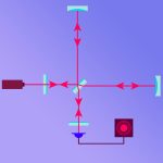
The following image shows the basic setup used in modern gravitational wave detectors, such as the American aLIGO, in perspective:

Schematic setup of an interferometric gravitational wave detector.
From the light source L, the light pulses run to a kind of switch BS, the beam splitter. Half of the pulses arriving there continue straight ahead to the mirror M2. The other half is deflected by 90 degrees and runs to the mirror M1. After a certain distance, the pulses hit one of the mirrors, where they are reflected and returned to the beam splitter.
Also, of the pulses arriving from direction M1 (or M2) at BS, actually only half is directed to the light detector D, the other half back to the light source L. We ignore this second beam splitting, because it does not matter for the basic principle, and pretend that all pulses arriving from M1 or M2 at BS are directed straight to the light detector D. (To avoid confusion, D refers to the “light detector”; when “detector” is mentioned without any addition, the whole arrangement is meant, including light source, mirrors and everything around).
We consider mirrors and beamsplitters as free particles whose distances are influenced by the gravitational wave. Naturally, the course of the light pulses is influenced as well, similarly as above. The entire setup is a variation of a so-called Michelson interferometer. Why there are two light paths and why the beams have to be united at the end, will become clear further below.
In real gravitational wave detectors the distances between beam splitter and mirrors are very large – for the largest detectors of today, in the kilometer range – while light source and detector are quite close to the beam splitter. Therefore, the influence of the gravitational wave becomes important between BS and M1 or M2. The distances BS-M1 and BS-M2 are called the arms of the interferometric detector.
Crests and troughs of laser light
Light consists of recurrent wave crests and troughs (of the electric and magnetic fields, respectively). Waves react somewhat differently than particles when it comes to combining (“superimposing”) them at a beam splitter, for example. The combination of two particles is “twice as much particle as before”. The combination of two waves can be a stronger wave, but also – no wave at all. Or a complicated wave.
Here is an example of what happens when the different waves are recombined (“superimposed”) in front of the light detector. In my first example, green and red dots each arrive at the same time, wave crest meets wave crest, and wave trough meets wave trough.
The corresponding light dots are placed above each of the wave crests drawn in the next diagram for illustration purposes only. For orientation, the vertical lines indicate where the crests of the green wave are located: The result is shown in the bottom panel as a blue line, namely the sum of the two waves at each instant. The blue line oscillates much more than the individual waves. The result is bright light, “constructive interference”, more light than in each of the solitary waves:

Constructive interference of two identical laser waves causes laser light with an amplitude twice as high
In the case of our detector, it is exactly the opposite in the absence of gravitational waves. When green and red light points arrive at the detector (without a gravitational wave) at different times, this means that the crests of one beam meet the troughs of the other one and the other way around. As a result, the waves cancel each other out almost entirely (“destructive interference”), and the detector sees only very faint light or none at all. The next image illustrates this situation, the blue line at the bottom again represents the sum of the two above:

Destructive interference of two identical laser waves produces extinction of light
The lower blue line remains at zero. In the absence of gravitational waves, obviously no light arrives at the light detector at all. (This is almost, but not quite, the case with real detectors.) However, where a gravitational wave passes through the detector, the light waves look like this:

Superposition of two laser beams under the influence of gravitational waves results in a complex signal at the detector
When a gravitational wave passes through, at once, a signal appears at the light detector! This is, at least in a very simplified version, the measuring principle of the interferometric gravitational wave detectors.
Further Information
The basic principles of relativity are explained in our Elementary Einstein tour, particularly in the chapter on gravitational waves.
Find related spotlights in the category gravitational waves.
Colophon
is a scientist at the Albert Einstein Institute in Hannover who is involved in the maintenance and development of the gravitational wave detector GEO600.
Citation
Cite this article as:
Peter Aufmuth, “Interferometric gravitational wave detectors” in: Einstein Online Band 13 (2021), 1009
Further Articles
 Catching the wave with light
 Observation of Gravitational Waves from a Binary Black Hole Merger
 LISA – Hunting waves in space
 Cosmology / Elementary Tour part 2: Reddening galaxies
 Spezielle Relativitätstheorie / Einsteiger-Tour Teil 1: Relativ zum wem oder was?
 Spezielle Relativitätstheorie / Einsteiger-Tour Teil 3: Die Relativität von Raum und Zeit