

A subtle change in direction: Geodetic precession
In Einstein’s theory, gravity is related to spacetime curvature. This text explores what curvature is – and how the way it influences geometry can be measured directly, with the help of gyroscopes.
An article by Markus Pössel
In Einstein’s general theory of relativity, gravity is directly associated with the geometry of space and time. In particular, spacetime around a massive body is curved – for instance, the geometry of space is different from the usual Euclidean geometry taught in high school. One of the consequences concerns the possibility to judge the orientation of objects that are at some distance from each other – do two arrow-shaped objects, for instance, point in the same direction or not?
Comparing arrows in the plane: Parallel transport
Four-dimensional curved spacetime is extremely difficult to visualize. Fortunately, you can get a feeling for many aspects of its geometry by looking at simpler objects such as two-dimensional surfaces. So let’s imagine that we are looking at a two-dimensional plane and at two arrow-shaped objects. Do the two arrows point in the same direction? How do we tell?
In the simplest case, the basepoints of the two arrows are at the same location, and we can measure directly the angle between the two arrow shafts. If it is zero, the two arrows point in the same direction:

What if the basepoints are not the same? Usually, we have no difficulty in judging direction even then. We only need to imagine what the first arrow would look like when shifted to the location of the second arrow, and whether their directions would then coincide. More explicitly, we can define what it means to shift an arrow without changing its direction (“parallel transport”, in the language of geometry). On a plane, the recipe is simple: Draw a straight line from the arrows initial basepoint to wherever you want to shift it. Move the arrow’s basepoint along that line, taking care to keep the angle between line and arrow shaft constant:

After the shift, the arrows can be compared directly, as their basepoints are now the same.
Shifting along a closed path
What about shifting along more complex paths – for instance, the combination of several pieces of straight lines? In the plane, it turns out that we can take any path we like to get from the old to the new basepoint. The shifted arrow will be the same in all cases.
In particular, if we shift along a closed path such as this triangle, once we have returned to our starting point, the arrow points in exactly the same direction as it did originally:

You might wonder why I am even making this statement. Isn’t it obvious that, if we shift an arrow around a closed path keeping its direction constant, it will be the same after the shift as before? In the plane (and in ordinary, everyday three-dimensional space), yes. But this changes once curvature comes into play.
Arrows on a curved surface
Now, let us look not at a plane, but at the curved surface of a sphere. A direction on the sphere (such as North, South, East, West and the many directions in between defined here on earh) can be represented by an arrow that is tangential to the sphere’s surface. More precisely, at every point of the surface, we can attach what is called the “tangential plane”, which fits as smoothly as possible against the surface at that particular point – here is an example, complete with an arrow lying in that plane:

Let us zoom in closer…

…and view the plane edge-on

There, you can see that the plane (now visible only as a thin line, since you are viewing it edge-on) and the arrow are indeed tangential to the sphere’s surface.
Transporting arrows on a spherical surface
Now that we have defined tangential planes and arrows that live in them, how can we shift such arrows while keeping their direction unchanged? There are no straight lines on the surface of the sphere, but there are lines that are as straight as possible: So-called great circles, circles that have the same center and the same radius as the sphere, such as the equator girding the earth, or the meridians running from pole to pole. If we shift the basepoint of our arrow along part of such a great circle, taking care that the angle between the arrow’s path and the arrow shaft remains constant at every point of the way, this is the closest we can come to shifting the arrow without changing its direction.
There is a subtlety here: In order to visualize a sphere, we usually imagine it the way it is embedded in three-dimensional, ordinary space. But this is just a way of picturing the sphere – what we are interested in, the directions and the shifting of arrows, is concerned solely with the sphere’s two-dimensional surface and not with the surrounding space. In particular, when we shift an arrow in the way described above, that is not the same as keeping the arrow’s direction constant in the surrounding three-dimensional space – on the contrary, as the surface curves away, the arrow, following that curvature in order to remain tangential, necessarily has to shift its direction in space.
A not-so-subtle change brought about by curvature
One direct consequence of curvature is that, when we transport the arrow along a triangle made up of parts of great circles (the analogue to our earlier triangle made up of straight lines), then when it returns to the starting point, it will not, in general, have the same direction as before the shift. Here is an example where we start at the equator with an arrow pointing straight West, shift the arrow along a meridian to the North pole, shift it down again along a different meridian until we reach the equator, and then shift it along the equator back to the original position:

In this case, there is an angle of 90 degrees between the direction of the arrow before the transport, and after. If you would experiment with different paths on a sphere, you would find that this angle is proportional both to the area enclosed by the path and to the inverse of the sphere’s radius. The latter is a measure of the sphere’s curvature: The surface of a sphere with large radius is curved only slightly. For instance, take that part of the earth’s surface we can overlook while going after our business… the part of the earth’s surface we are used to overlooking appears almost flat (uncurved) to us. The smaller the radius of a sphere, the greater its curvature.
Defining curvature in more than two dimensions
In fact, such changes in direction are what physicists and mathematicians use to define curvature in more general space. At every point P in such a space, choose two directions and take a vector. Shift your vector first a little distance d in the one direction, and afterwards shift it a little distance D in the second direction. Remember to keep the path along which you are shifting as straight as possible, and to keep the direction of the vector as constant as possible. Next, repeat the operation, but change the order of shifts – now you start by shifting the vector in the second direction, followed by a shift in the first direction, in just the right way to obtain something akin of a parallelogram. Here is an animation of the procedure:

From what you have read about the subtle changes of direction on the surface of a sphere, you will not be too surprised at the result shown in the animation: In general, the direction of the vector transported along the one path will differ from that transported along the other part.
In fact, transporting the same vector along two different paths to another point is the same as transporting a vector along a closed path. Start with the green vector as it is shown as the point Q. Transporting that vector back to P would give our original vector. Transporting that original vector along the red path back to Q would give the red vector shown at Q, so the difference in direction of the two vectors at Q is really the same as the difference in direction we would have obtained by transporting one of them along the closed path formed by the parallelogram.
This little scenario is directly related to the definition of the mathematician’s standard measure of curvature, which goes by the imposing name of “Riemann curvature tensor”. The Riemann curvature tensor is a function – a mathematical machine, if you will, into which you can feed a number of mathematical objects and which will process this input to give you a specific result. More concretely, if you feed this curvature tensor all the information about the little parallelogram scene shown above – one specific point in space, the vector you would like to transport, the two directions and the two path lengths d and D -, the result it will give back is the difference between the green and red vectors at Q.
In the case of our two-dimensional sphere, the resulting difference depended on the area enclosed by the path and on a single number characterizing the curvature – the radius of the sphere. In a higher-dimensional space, there are more ways to choose different directions, both for orienting the little parallelogram and for defining the vector, than on a two-dimensional surface. Correspondingly, curvature at each point is not only defined by one number, but in fact by n²·(n²-1)/12 numbers. The curvature at each point in four-dimensional spacetime – a central ingredient in formulating general relativity – is characterized by 20 numbers.
Gyroscopes in spacetime
But back to matters somewhat less abstract. In spacetime, there is a rather concrete realization of vectors and of transporting them while keeping their direction as constant as possible: Gyroscopes!
In deep space, far away from all outside influences, the axis of a gyroscope will faithfully keep its direction:

This constancy in direction is directly related to a physical law governing the conservation of angular momentum, which states that, unless the gyroscope interacts with its environment, its axis direction must remain constant (background information about angular momentum can be found in the spotlight text What figure-skaters, planets, and neutron stars have in common).
On earth, one can try to recreate such an interaction-free environment by placing the gyroscopes in gimbals – a special arrangement of rotating rings that let the gyroscope keep its direction even when the orientation of the base to which it is fixed is changing:
More sophisticated versions of this arrangement are the basis for (mechanical) gyroscopic compasses, which have been in use on ships since the mid-nineteenth century. If the axis of rotation is made to point true North initially, then it will continue to point North even when the ship it is installed on changes direction. Another application of such “inertial navigation” equipment is in planes or in missiles, where a set of gyroscopes can provide a set of constant reference direction for measuring the plane’s or the missile’s orientation in space.
Geodetic precession
In all these applications, it is assumed that moving the gyroscope will not change its direction. While this is true in the framework of classical mechanics and also in special relativity matters are not so simple in general relativity, where gravity comes into play. Still, there is a simple way to transport a vector – represented by the axis of rotation of a gyroscope – in curved spacetime: Just let go! More precisely: A gyroscope in free fall is general relativity’s equivalent of transporting a vector with as little change in direction as possible – the analogue of our transporting vectors in a plane and on the surface of a sphere.
But transporting a vector with as little directional change as possible does not mean that there will be no change at all. Where spacetime is curved (notably in the vicinity of a mass), there will be a subtle change in direction – just as in the case of our curved spherical surface.
Imagine a gyroscope falling freely around the earth, 640 kilometres above the surface, tracing out a closed, circular orbit as shown in the following animation. At one particular point on its orbit, we choose the direction of the gyroscope axis to be parallel to light received from some particular, very distant star, our reference star:

As shown here, after the gyroscope has completed one orbit, its orientation will differ ever so slightly from the way it started out – we can check this by comparison with the light from our reference star.
The shift in the direction of its axis is minute. For a gyroscope on a circular orbit, 640 kilometres above the surface of the earth, the axis direction would shift by 340 billionths of an angular degree per orbit (corresponding to a shift of around 6.7 arcseconds per year). In order to render this shift visible in the animation, this shift has been exaggerated by a factor of 50 million.
The effect is called geodetic precession. In general, precession is the shift in the direction of a gyroscope’s rotation axis brought about by an external force; in this case, though, the effect follows from simply moving along in free fall, along a straightest-possible line through spacetime, a geodesic. An alternative name is de Sitter precession, after the Dutch astronomer Willem de Sitter who, in 1917, was the first to derive this consequence of general relativity.
The orbit in our example is similar to the one of Gravity Probe B, a satellite that was launched in 2004 to measure not only the effect of geodetic precession but also what is called frame-dragging – a shift in direction that occurs in the vicinity of a rotating mass. In order to do so, Gravity Probe B monitors the orientation of its internal gyroscopes relative to a distant reference star – not only at one point of its orbit, but continuously, taking into account effects such as light deflection which change the direction of the starlight as the satellite moves along its orbit. Results from this mission are expected in mid-2007.
Up to now, geodetic precession has been measured mainly with the help of natural satellites. Notably, it is possible to view the earth-moon system as a gigantic gyroscope, its axis of rotation defined by the motion of the moon around the earth:
By monitoring the system, it was possible to test the predictions of general relativity to an accuracy of a few percent.
More recently, geodetic precession has been observered in binarypulsar – systems in which two super-dense neutron stars orbit each other. Near such compact objects, curvature is so pronounced that the shifts in direction amount to more than one angular degree per year!
Further Information
For the relativistic ideas behind this spotlight topic, check out Elementary Einstein, especially the chapter on General Relativity. Related Spotlights on relativity can be found in the section General Relativity.
A java applet that lets you drag around an arrow on a sphere interactively can be found on John Sullivan’s Spherical Geometry Demo page.
Colophon
is the managing scientist at Haus der Astronomie, the Center for Astronomy Education and Outreach in Heidelberg, and senior outreach scientist at the Max Planck Institute for Astronomy. He initiated Einstein Online.
Citation
Cite this article as:
Markus Pössel, “A subtle change in direction: Geodetic precession” in: Einstein Online Band 06 (2012), 06-1001
Further Articles
 Cosmology / Elementary Tour part 1: The expanding universe
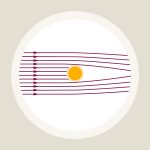 Allgemeine Relativitätstheorie / Einsteiger-Tour Teil 4: Verbogene Lichtstrahlen
 Relativity and the Quantum / Elementary Tour part 3: The need for quantum gravity
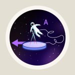 Special relativity / Elementary Tour part 2: The principle of relativity
 Relativity and the Quantum / Elementary Tour part 2: Evaporating black holes?
 Schwarze Löcher & Co. / Einsteiger-Tour Teil 2: Schwarze Löcher